
Περιγραφή
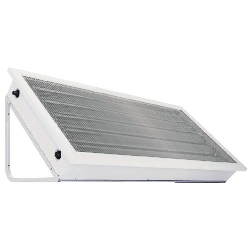
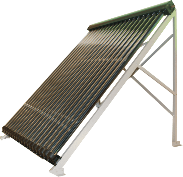
ΗΛΙΑΚΟ SOLLER Σωληνες κενου
ΙΔΑΝΙΚΗ ΛΥΣΗ ΓΙΑ ΣΥΝΔΙΑΣΜΟ ΖΝΧ ΚΑΙ ΕΝΔΟΔΑΠΕΔΙΑΣ ΘΕΡΜΑΝΣΗΣ
ΣΕΤ ΜΕ 18 ΣΩΛΗΝΕΣ 1000 euro
ΣΕΤ ΜΕ 26 ΣΩΛΗΝΕΣ 1400 euro
caused by freezing of the water inside.
1.7 Hail Resistance
The glass evacuated tubes are surprisingly strong and able to handle significant
impact stresses once installed. Testing and impact stress modeling proves that the
tubes are able to withstand impact hail up to 25mm/i”indiameter when installed at
angle of 40°or grater. The ability of the evacuated tubes to withstand impact from
hail is greater influenced by the angle of impact and so installing the collectors at
low angles to reduce their impact resistance. However, even when laying flat,
impact by hail up to 20mm/3/4”in size will not cause breakage. It is recommended
that in areas prone to large hail(>20mm3/4”) the solar collector should be installed at
an angle of 40°or grater to provide optimum protection. As many populated areas in
the world fall within the latitude of ±30~70°, this angle is generally a common
installation anyway. If in the unlikely circumstance that a tube should become
broken tubes, however a reduction in heat output will result (depending on how
many tubes are broken).
1.8 System design and installation
Please read all installation instruction carefully before beginning system design or
installation, the system configuration may need to be customized to suit the specific
requirements. Please ensure that any system design meets local building , water
quality regulations.
2. Unpack and Inspect
2.1. Tube inspection
Open the tube box (es), which contain both evacuated tubes and heat pipes. Check to
make sure the evacuated tubes are all intact and the bottom of each tube is still silver.
If a tube has a while or clear bottom, it is damaged and should be replaced. Each
evacuated tube contains a pair of metal heat transfer fins. As soon as the evacuated
tubes are removed from the box, please put on the rubber tube caps, which are
located in the manifold box. This will protect the bottom tip of the glass tube from
being broken if knocked. Do not remove and expose the tubes to sunlight until you
install them, otherwise the inner tube and heat transfer fin will become very hot. The
outer glass surface will not become hot.
2.2. Heat pipes handling information
A.Strictly no weight on the packages ;
B .Be careful when take parts from the carton ;
C.Strictly no extrusion for the copper pipe ;Anyway ,if heat pipes are bent during
handing, don’t worry as they are not easily damaged. Just ensure they are relatively
straight before inserting into the evacuated tube.
2.3.Frame
Unpack the standard frame kit that is packed together with the manifold, if a
flat roof frame or low pitched roof frame is being used, those components will
be packed separately from the manifold. It may be necessary to purchase bolts
or other fasteners to suit the installation surface.
3. Plumbing
3.1. Plumbing Connection
Once the frame has been mounted and the manifold attached, the manifold
header may be connected to the system plumbing.
3.2. Choice of Piping Material
13mm OD, or 15mm OD copper piping is generally used for most solar
collector installations. As the flow rate is slow, a large diameter pipe is
unnecessary and will only increase system costs and heat loss.
3.3. Pressure Levels
Regardless of the installation configuration, pressure release values,
expansion vessels and/or other pressure control devices must be installed.
The solar loop should be designed to operate at no more than 800kpa(PRV
may be 850kpa).(800kpa=8bar=116psi)For installation where mains pressure
water is used, the system should ideally be designed to operate at a pressure of
<500kpa, achieved by use of a pressure limiting/reduction value.
Page 5 of 16
3.4. Temperature value
It is recommended, and may be required by regulations, that a temperature control
device(tempering valve) be fitted into the hot water pipe between the water heater
and bathrooms and en-suits to reduce the risk of scalding. This is achieved by
controlling the water temperature to below 50℃/122F(temperature may be
adjustable) .
3.5. Temperature Sensor Insertion
The solar controller’s temperature sensor should be coated with a thick layer of
thermal paste and inserted into the sensor port to the full depth. If the fit is too
loose, slide a piece of copper plate or wire in beside the sensor, seal the sensor port
opening with silicone sealant to prevent water ingress. Ensure that sensors used on
the collector are high temperature rated (up to 250℃/486F),
in particular the cable.
3.6. Stagnation and Overheating
Stagnation refers to the condition that occurs when the pump stops running,
due to pump failure, power blackout, or as a result of a high tank temperature
protection feature built into the controller, which turns the pump off. If a PTRV
is installed on collector inlet or outlet the collector will continue to increase in
temperature until the limit of the temperature relief valve is reached, at which
point hot water will be dumped from the system. If a PTRV is not installed on
the collector, steam will form in the header. Eventually some steam may feed
back the storage tank via the return line. The PTRV on the tank will open to
release pressure or heat as required. Under such conditions the manifold will
normally reach a maximum temperature of around 160 / ℃ 320F. Generally the
heat returning from the collector in the form of steam is not enough to affect a
continued increase in tank temperature lie. Heat input <tank heat losses)
Under normal use stagnation should rarely occur as a result of pump stoppage,
since power blackouts normally happen during storms and not clear sunny
weather. High tank temperature protection should only occur when hot water is
not used for several days (when on holiday), and only during periods of strong
sunlight(summer). If leaving the house for an extended period of time(more
than2-3 days), it is advisable to cover the collector panel or design the system
with a heat dissipation device or alternative use for the heat, thus preventing
overheating of the system and collector stagnation. Stagnation of the solar
collector will not damage the solar collector, however insulation used on the
piping close to the manifold inlet and outlet should be able to withstand
temperatures of up to 200 /395F. (eg. Glass wool or ℃ mineral wool-with an
exterior wrap of aluminium foil, thus protecting against the elements)
Page 6 of 16
4. Frame Installation
4.1 Installation for flat type solar collector
1.Connect the front leg and back leg with nuts ,and fix the side legs on the front
legs and back legs
2.Connect the front legs with X lacing bar ,intall the guard on the bottem,and
there are middle-front legs for type with 24 tubes and more than 24 tubes,fix the X
lacing bar which is on the left and right side of middle legs with connector,and fix
such connector on the middle legs.
Page 7 of 16
3. Connect the back legs with X lacing bar and there are midle-back legs for types
with 24 tubes and more than 24 tubes,fix the X lacing bar which is on the left and
right side of middle legs with connector,and fix such connector on the middle legs;
4.Install food pad on the all legs;
5.Fix the manifold on the front legs,fix the nut and don’t screw it down firstly;
6.Install the vacuum tube: firstly fix the vacuum tube on the guard ,then take down
the adjuster of tuber holder according to the counter clockwise ,put the vacuum
tube including heat pipe thermal conductor and plug into the tube holder,smearing
thermal conductive silicone (HZ-KS101) on the conderer of heat pipe ,and then
insert into the manifold and plug the vacuum tube until it is on the bottem of the
manifold,install and fasten the adjuster of tube holder。Firstly intall the vacuum
tube separately on the right and left side,adjust the manifold and fasten the nuts